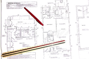
Are you having an architect prepare construction documents for your house renovation/addition/alteration? Your architect’s drawing will have a certain order to them as well as many symbols and line types as well as abbreviations and hatches. The following are some quick tips on reviewing and understanding the documents.
The Drawing Order:
The First Drawing
The first drawing in the set will have all the building data information which includes the square footage of existing and new. It will also have the volume calculation of your project. This is provided for the town to calculate your permit costs. Other key data includes Construction Codes that have been followed to create the documents as well as construction type
A drawing list will be on the first page to help you navigate the set.
General notes, which speaks for itself, which gives your general contractor some guidelines.
Depending on the scope of your project some of the following items could also appear on the first sheet; site plan which will show an overall plan of your property as well as the structure and how any addition is impacting the site by delineating the distances from front, side and rear yards which are dictated by local zoning regulations, demolition plans can be present to indicate what existing structure and utilities are being removed.
The Second Drawing
There is some debate out there as to what comes next but traditionally for my office it is the foundation plan. My drawings start from the ground (in this case below the ground) up. This is your basement plan or crawlspace depending on what route you go (https://www.aricgitomerarchitect.com/watch-your-footing/)
These drawing will typically have foundation details as well and structural notes.
The Following Drawings
The set follows with the floor plans, details, sections and elevations.
The Final Drawing
The last drawing in my typical set is the MPE which is your mechanical/plumbing/electrical drawing showing lighting and outlets as well as general notes regarding mechanical/plumbing/electrical work.
If your job is large enough and complicated a set of structural drawings maybe found towards the back of the set as well. But many times the structural information can be found directly on the floor plans.
Symbols/Hatches and More
Each set of drawing has many components to help the reader understand and navigate the project. The following is an abbreviated list of what you may find:
Section symbols and call-outs are a standard navigational tool architects use. This is basically a circle that is divided in 2 with a line and has a number or letter in the top half referring to the actual detail number and the bottom has the sheet number this detail is found. Sometimes these symbols also have an arrow associated with them indicating which direction the detail is drawn. You can sometimes find a symbols legend on the first drawing to guide you in understanding each symbol which could be for an interior elevation, details or a section.
Each individual drawing in a set, which could be hundreds, has a unique name and numbers (or letter) which helps you identify what you are discussing if you need to talk over the phone or communicate via email. In addition directly below the drawing name, you will find a drawing scale. The architect’s drawings are always drawn to scale (even though a general contractor is not permitted to scale a drawing – written dimensions rule!). This scale varies but typically a floor plan is drawn at ¼” = 1’-0” and details vary depending on the complexity and how much information needs to be conveyed. Architects use a triangular scale which has 6 different scales on it!
Lines types also vary throughout the drawings and depending on what drawing you are viewing the same line type may have a different purpose. For instance a hidden line (which is a dashed line) shown on a demolition plan will indicate an item removed, on a foundation plan it will typically refer to the footings, on the floor plan that hidden line could be referring to something above such as a soffit and on the elevation it could be indicating something behind. The architect will typically have a note to help guide the reader. Common line types on a set of drawings are; continuous, hidden, phantom, and center line.
Hatching (shading and architects refer to this as poche) is another method for architects to help clarify what is going on. In renovation work, if you see some form of hatching on a floor plan you can assume that is new work and un-hatched would be an existing condition. Typically in a foundation plan, you will see a cross hatch for new masonry walls, a speckled and free-form shaped hatch indicating concrete. Each plan will most likely have its own unique hatches indicating a typical condition. Look for the notes telling you what they are or a legend.
Dimensions are in every drawing. This is a critical component informing the user of sizes and spacing. Sometimes you will see a continuous string of dimensions or when not necessary and individual dimension may be found. In renovation work instead of cluttering up the drawings with an abundance of drawings, the architect will indicate a note align with existing. In addition, architects vary on how they dimension plans. Some will dimension to the centerline of a wall, others will dimension to the face of stud within the wall and then some will be in the camp of dimensioning to the actual finish wall surface.
Orientation is indicated on the floor plans with a north arrow which can be referred back the site plan to orient yourself to the project. Don’t assume on a set of documents that north is up.
Notes are needed to explain the details and plans. Each note has an arrow associated (unless it is a general note standing by itself) pointing to the item it is referring to aid the reader in a deeper understanding of the drawing.
Abbreviations are frequent and numerous (https://www.aricgitomerarchitect.com/omg-architects-natural-texters-not). This helps keep the drawing uncluttered. Architects use many abbreviations in their work and many are industry standards and some are made up. A set of drawings may have a legend of all the abbreviations. Some typical ones are; CMU, GWB, CONC, GALV, O.C., MIN, VIF, THK, WC and the list goes on and on! LOL
Doors are shown typically with a double thin line with an arc indicating the way the door swings and a dimension of the door are within that symbol. Some architects will indicate the size in feet and other in inches. For instance, a door could be 32×80 which is the same as 28x68 so be careful when checking door size.
This is a brief overview just to get you acquainted with the documents. There are much more components of the drawings but as you go through them you will understand them a little better and the more you review them the clearer they will be. They are created to allow the Building Official to review them and your contractor to construct your project so there will be some type of order to them and navigational tools will be there to guide them. Architects have been trained in many different offices with many different formats and styles and types that will follow an architect throughout his/her life so each individual architect’s sets may be slightly different in style and format but they are all going to get you to the ultimate result – your home!


